skip to main |
skip to sidebar
I try and stay away from making posts about stuff that you can readily find in the Bentley manual. The information in the Bentley concerning the Thermostat and Water Pump are very adequate and if you follow that information you will be able to complete these jobs with no problem.
What I thought that I'd do in this post is give a few tips I've discovered while doing these jobs four different times now.
The reason I did the replacement of the thermostat and water pump so soon is because I developed a leak. Actually it was leaking for a good year or so, but only occasionally. Once in a while I'd notice some coolant on the ground, I couldn't tell where it was coming from exactly, but I knew it was from the front of the engine, so more than likely it was the water pump. I like to change out the thermostat when I do a water pump since I've got everything apart anyway, so I ordered the things I needed. I got a new water pump, thermostat and housing, radiator hoses and belts. I could tell the belts were getting wet from the leak and figured it would be a good idea to change them out too.
Here are some tips that should make your job a bit easier if you have the Bentley and follow it.
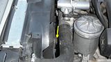
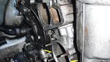
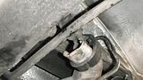
To get to the water pump and thermostat, you need to remove the fan and housing. They say you need a special tool to hold the fan pulley, but you don't really need it. I used a 1 1/4" open end wrench to loosen the fan nut. Remember, it is a left hand thread, so you turn it the opposite way to loosen it. Here is the tip you can use to get it loose without the special tool. If you look at the picture below, you can see where I've drawn the arrows. Take a mallet, I used a rubber one and hit it in the direction shown. It probably won't break loose the first time, maybe not even the 10th time, but it will eventually break loose. I started using a propane torch to heat up the fan nut so it would break loose easier. If it won't come loose without it, try the heat.
This pic shows the location of the fan nut without the wrench:
 This pic shows with the wrench:
 With the fan and housing removed, you can now proceed. Before you attempt to remove the thermostat housing or water pump, you need to drain the coolant out of the system.
Here are a couple of tips that might help.
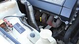
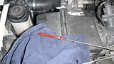
First off, I jack up the front end of the car and put two buckets under the radiator, see pic:
With the fan and housing removed, you can now proceed. Before you attempt to remove the thermostat housing or water pump, you need to drain the coolant out of the system.
Here are a couple of tips that might help.
First off, I jack up the front end of the car and put two buckets under the radiator, see pic:
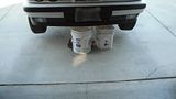 Make sure all of your heater settings in the car are set to HOT, best way to do this is to turn on the key, turn the knobs and wait for about 30 seconds and then turn off the key. Then I open the radiator drain. I completely remove the drain plug and to do that, you have to remove the retaining pin (see pic, you may not have the retaining pin, one of my 525i's was missing it the first time I did this). It drains much faster without the plug in the hole.
 Make sure you remove the radiator cap too so the coolant will drain quicker.
Once the radiator is drained, you still need to drain the rest of the coolant in the block.
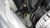
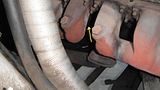
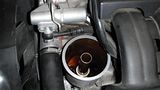
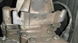
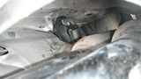
You do this by removing the block plug. The block plug is located on the passenger side of the motor right between the exhaust headers. Depending on how much of the original shielding you have underneath your car you may have to remove several panels to let the coolant drain properly. Both my cars had only a couple of pieces of the shielding up, so it came apart easily.
This series of pics shows the location on the block plug:
Make sure you remove the radiator cap too so the coolant will drain quicker.
Once the radiator is drained, you still need to drain the rest of the coolant in the block.
You do this by removing the block plug. The block plug is located on the passenger side of the motor right between the exhaust headers. Depending on how much of the original shielding you have underneath your car you may have to remove several panels to let the coolant drain properly. Both my cars had only a couple of pieces of the shielding up, so it came apart easily.
This series of pics shows the location on the block plug:
 Once the coolant is drained, you can finally get down to business.
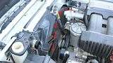
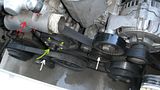
This picture shows several different things. The location of the thermostat housing and it's bolts (red arrow housing, dots are bolt locations). Yellow arrow shows threads of water pump where fan attaches to, yellow dots show bolts that hold fan pulley to the water pump. White arrows show locations of the tensioner pulley's for the belts. You will use one of a few different things to remove the belts, either an allen wrench, torx wrench or socket wrench. Just depends on how your car is set up.
Once the coolant is drained, you can finally get down to business.
This picture shows several different things. The location of the thermostat housing and it's bolts (red arrow housing, dots are bolt locations). Yellow arrow shows threads of water pump where fan attaches to, yellow dots show bolts that hold fan pulley to the water pump. White arrows show locations of the tensioner pulley's for the belts. You will use one of a few different things to remove the belts, either an allen wrench, torx wrench or socket wrench. Just depends on how your car is set up.
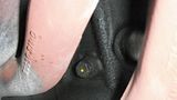
 Once you have the belts and radiator hoses removed, you can work on taking the thermostat housing and water pump out. Thermostat housing is easy, just remove the four bolts. The water pump can be a bit more challenging, but not that bad. If you look in the Bentley, it tells you that you need two M6 bolts to draw the water pump out of it's seat once you have removed the four mounting nuts. I looked high and low for those M6 bolts the first time I did this job. I went to the local BMW Dealer and even they didn't really know what I was talking about, but I finally ended up with what I needed. To make your job easier, the three small bolts that hold the thermostat housing on are M6 bolts and work perfectly for drawing out the water pump. You just thread them into the ears on either side of the water pump and slowly turn them a little at a time and it will draw the pump out. One of my cars didn't even need to have that done, the pump pulled out easily by hand.
If you look at the picture below, you can barely see where the M6 bolts push against to draw the pump out, I didn't take a picture of the pump installed, this is after I had already removed the pump. You can also see above where the thermostat and housing fit.
Once you have the belts and radiator hoses removed, you can work on taking the thermostat housing and water pump out. Thermostat housing is easy, just remove the four bolts. The water pump can be a bit more challenging, but not that bad. If you look in the Bentley, it tells you that you need two M6 bolts to draw the water pump out of it's seat once you have removed the four mounting nuts. I looked high and low for those M6 bolts the first time I did this job. I went to the local BMW Dealer and even they didn't really know what I was talking about, but I finally ended up with what I needed. To make your job easier, the three small bolts that hold the thermostat housing on are M6 bolts and work perfectly for drawing out the water pump. You just thread them into the ears on either side of the water pump and slowly turn them a little at a time and it will draw the pump out. One of my cars didn't even need to have that done, the pump pulled out easily by hand.
If you look at the picture below, you can barely see where the M6 bolts push against to draw the pump out, I didn't take a picture of the pump installed, this is after I had already removed the pump. You can also see above where the thermostat and housing fit.
 Once you get to this point, the Bentley does a very good job of instructing you on what to do. It's pretty much just reverse of the removal to install. Make sure you use BMW coolant and distilled water, not the green stuff to refill the system. All of the torque specs are listed in the Bentley and should be followed. Other than that, good luck with your project.
Back in February, I started an experiment with an oil additive called Auto-Rx. I was having some lifter noise at start up in my 93 BMW 525i, especially when it was really cold (at least for the California High Desert). Read this post for more information.Here is an update. I just finished the first rinse phase of the experiment. So far I'm pretty impressed with the results.When I started this back in February, I was averaging about 25.5 MPG. As of right now, the last four tanks of gas have averaged me about 27.5 MPG. The motor seems to be running cleaner and I'm not burning/using anywhere near the amount of oil I used to before the first phase of the treatment. I know it's running cleaner because I don't get any soot build up on the tips of my exhaust pipes. Prior to the treatment, I was always wiping soot off the chrome tips, now none. I also used to burn about a quart of oil every 1K miles, last time I added, I had over 2K miles and it didn't even need a whole quart. Another thing is that nearly all of the little oil leaks I had before are gone. I get an occasional little drip, but nothing like it used to be.When I did the first phase oil treatment, I also added the Auto-Rx to my transmission, differential and power steering according to their direction for each. Didn't notice much change to the differential, not saying it didn't benefit from the treatment, just that I didn't notice the difference. As far as the power steering, all of the little leaks in that system have gone away, and it feels a bit tighter in the steering too, that could be the new tires I put on a while back. But the leaks are history and I know that the Auto-Rx is responsible for that.The big change came with the transmission. About 300 miles after adding the product, I was leaving work to go home one morning. I drove out of the parking lot onto the street up a slight incline. As I did so, it didn't feel like normal. Probably 200 yards from the parking lot the transmission downshifted extremely hard, went about another 50 feet and then did it again. I stopped along side of the road thinking I had just blown up the tranny. I got out of the car looked under to see if I could detect any problem, no leaks, so I figured I might as well try to see if it would drive. Much to my surprise, it acted like there was nothing wrong. I drove home, all 40+ miles without incident. After putting on about another 700 miles I changed out the trans fluid and filter per the instructions to get the product out of the system. I drove the car probably another three thousand miles, when I experience the same hard downshifting again, almost exactly in the same spot that it happened the first time. This time, when I got to the stop sign, I just kept going... no problems again. It's now about 2000 miles since the last incident, and it seems to be just fine. Better than fine actually. The tranny shifts much more crisply and doesn't hesitate like it used to. I'm convinced that the Auto-Rx treatment did wonders for that old Transmission. The car has over 200K miles on it, not sure if the trans has that many, but I know it was abused before I bought the car due to the condition of the fluid and filter the first time I changed it after I bought it.So, I'm pretty happy with the results I've had in this car. When I did the treatment on this car, I also added it to my wife's 03 Honda CRV and my daughters 95 525i. The Honda was just starting to leak some oil, but stopped shortly after adding the Auto-Rx. My daughters 525i was averaging about 17MPG, mainly because she drives all short trips, no highway driving. I checked the mileage on it recently, and it is getting almost 19MPG now. I know she hasn't changed the way she drives.Lastly, here are a few pictures I took yesterday of the oil filter housing top and retainer bolt, dip stick and inside of filter housing. I started the second cleaning cycle with this oil change. If you checked out the previous post, it doesn't look like much of the varnish had gone away from the pieces of the housing. I didn't take any pics of the dipstick and bolt the first time, but I can tell you that both of them were the same brown varnish color before the treatment. Now they are back to their natural colors. 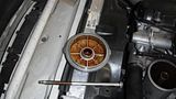
 Anyway, this is all FYI. Feel free to contact me if you have any questions. And, no, I'm not an employee of Auto-Rx. I just feel when you find a good product you should let people know about it.
One day before leaving for work, I was cleaning the windows on the 93 525i. I finished up cleaning the rear window and was about to go put my window cleaner and dirty rags away when I noticed some dirt on the chrome tips to the exhaust pipe. I bent down to wipe it off and when I touched the pipes, it moved about two inches to one side. It shouldn't have done that. I got down on one knee and looked up under and found that both of the hangers to the muffler had rotted away. One was completely gone nowhere to be found the other was just about half there hanging from the top mount. I decided that it wouldn't be a good idea to drive it that way.I got in my SUV and drove to work. While there, I looked around to see if I could get the hangers locally. I check AutoZone, they didn't carry them, NAPA had them, but they were special order and cost about $5 each. I looked at autohausaz and they had them for about $2 each. I needed to do a few other things that I'd been putting off, so I went ahead and ordered everything that I was going to need to take care of the projects I wanted to do.For this post, I'm going to focus on the Exhaust Hangers and Rear Trans mounts. I ordered the front mounts too, not knowing if I needed them, but thought I'd rather have them and not need them than vice-versa.As always, the parts came quickly, actually before I could do the work. So after sitting in my garage for several days, I finally got the time to work on the projects I wanted to do.I had known that the rear trans mounts were cracked for almost two years. I didn't have them when I could have used them when I replaced the guibo and the center driveshaft bearing when I first bought the car. I figured if it got real bad, I'd do it later. Since I was possibly going to have to drop the exhaust system out of the car, I thought I might as well do it while the exhaust isn't in the way. A side note, I had been having a weird vibration when starting from a stop. Between 15 and 20 MPH and about 1700-2000rpm, there was this very fast vibration. I thought it had to do with the tires and changed them, but that didn't solve the problem. I then remembered that the rear trans mounts were cracked and that they had probably gotten worse. I also thought that with the exhaust hangers gone, that could possibly be causing the vibration also. So, not having any repair instructions from the Bentley manual for either of these repairs, I just sort of winged it. Here is what I did...I put the car up on jacks as high as they would go. Then I crawled under the car to check on the rear trans mounts. Surprisingly, it appeared that it would be a fairly easy job. I will explain along with pictures I took.This picture shows the cross member that the mounts attach to. The green dots show the bolts that mount to the undercarriage (there are four bolts, one isn't visible on the photo). The red dots show where the mounts attach to the cross member and the transmission.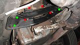 I took my floor jack and supported the transmission under the sump. I just took the weight off of the cross member. I used a piece of wood to distribute the load across the sump instead of having one small spot carry the load. Once that was done, I removed the four bolts holding the cross member. When it was loose, I pulled it off and both the mounts came with it, even though I should have had to remove the nuts that attached them to the cross member.This picture shows one of the old mounts next to one of the new mounts:
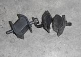 As you can see, the old mount wasn't just cracked, it was torn all the way through. Both of them looked like that. I had to remove the part that attached to the transmission. Once I did, this is what it looked like:
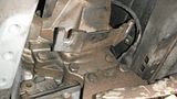
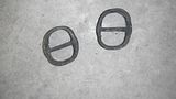
 After I got the broken parts off of the transmission, I then installed the new ones on the transmission first. Just make sure you orient them correctly, the mounts are not the same, there is a right and left sided one, also it appears you have to make sure you put the correct side to the transmission and the cross member.I made sure the studs from the mounts went through the cross member and then threaded the mounting bolts to the cross member. I would suggest that you do it however you think would be easier. Couldn't find any torque specs for the bolts, so I snugged them up to about how tight they were to remove them.Now for the Exhaust Hangers...Here are some pictures of the front hangers on and off the car, as you can see they were getting ready to fail also:
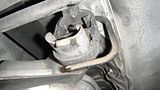
 For some reason, I didn't take any pictures of the new hangers before I installed them. I can't figure how to explain how I replaced to front hangers. You sort of have to thread them on the holders that are attached to the undercarriage and then pull them over the parts on the exhaust system. I found it easier to place my floor jack under the center muffler and jack it up a bit so I didn't have to stretch the hanger so much. I used a couple of screw drivers to help manipulate the hangers too.Here are some pictures of the new ones installed, I figured I took the picture, I might as well show them:
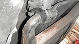
 Once the front hangers were in place, I left the floor jack in place and started the rear hangers.These were a bit more difficult. It would have been much easier to do if the exhaust was dropped, and if you have the stock muffler in place you may have to drop the system to replace them. In this car, I have two glass packs in place of the OEM muffler, so there is a bit more room to work around. I also think that the reason these hangers failed after not even two years is because they are exposed to way more heat with the glass packs instead of the OEM muffler.These pictures are of the right and left side hangers installed:
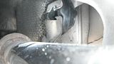
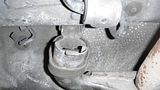
 You can see that the holders are two piece. One attached to the car and one attached to the exhaust. I put the hanger on the part attached to the car first and pulled it down into place. I then added the lower holder. It wasn't easy with the little room there. I used a bit of grease so it would slide through the opening easier. I wish I could give you some trick to make this easier, but I don't know one other than dropping the whole system, then you can get to the holders much easier. When I put them on just after I bought the car, the exhaust system was out of the car, so all I had to do was hang both holders and then fish the studs from the holder through the mount on the muffler. Here is a picture from below of both hangers installed:
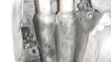 That's it for now, good luck if you're trying to do this.Next up... Water pump, Thermostat and Coolant Replacement.BTW... The vibration I talked about is gone, but I'm not sure if the Trans Mounts or the Exhaust Hangers fixed the problem, Oh Well...
Not too long ago, I started having some weird problems with my 93 525i. It usually happened right after I started the car on cooler mornings. I would drive for a bit then when I'd get to a stop, the car would have a loping idle and want to sort of surge forward. If I put the car in neutral it would take a few seconds, but the idle would smooth out. It didn't happen very often, but it was still bugging me. I hooked up my code reader and there were no codes. Thought it might be a vacuum leak somewhere, so I checked and found nothing. Then the problem stopped for several weeks.One morning I went out to go to work, cranked the starter and it wouldn't fire. Tried a few more times and it wouldn't start. Didn't have time to mess with it, so I drove my other car. The next day when I got home from work, I was going to find out what happened. I went out to the car, cranked it over and it started right up. I came away scratching my head over that.It ran fine for about another month. I had driven home from work and had to park in a place other than my normal spot because my daughter had a bunch of friends over. Later in the afternoon, they had all left so I moved the car, it ran fine. It sat there all night until I went out to drive the car to Church. I cranked it, the motor acted like it wanted to start, but quickly died and then nothing. Over time, I had found that you could hear the electric fuel pump fire up before you start the car. If I put the key to the #2 position, it would make a short whirring noise and then shut off once it pressurized the system. The morning that I tried to start it before Church, the whirring noise was more of a grinding noise. I tried starting it several more times during the day and nothing. I decided that the fuel pump was DOA. I ordered a new one the next morning from autohausaz. I had to wait to make sure that I got the correct one. Apparently there are two different versions that work on my car, so I needed to remove the old one to make sure I ordered the right one. The two versions were about $70 different in price, so I was sure that mine would be the more expensive one. I got up early and started the job. I read the Bentley manual instructions on how to remove the pump, but skipped the part where it tells you to drain the fuel tank. Probably not the best way to do it, but it's what I did. All of those reports of gas tanks exploding are greatly exaggerated, I know from experience.Anyway, the removal of the fuel pump/sending unit is fairly simple. I took some pictures and will post them with explanations below. BTW, when I took out the fuel pump, I discovered that I had the cheaper one, so I saved about $70, that doesn't normally happen to me, I always seem to be on the short end of the stick in situations like this.The fuel pump is in the fuel tank. To get to it, there is an access hole under the carpet of the trunk. Here is a picture: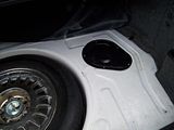 Here is a picture of it with the access cover off:
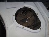 This picture is a close up of the top of the fuel pump/sending unit. To get it out, you have to remove the two fuel lines (I marked the left one with the electrical tape to make sure I put it back together right), the electrical connector and the eight mounting nuts that hold the plate to the tank. To remove the electrical connector, you have to slide the metal clip towards the back of the car. I put a small screwdriver in where I drew the green arrow and pried back and it came right off.
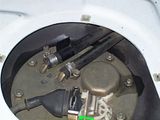 Once you have everything loose and disconnected, the plate will want to push upwards. There is enough play in the fuel lines and wiring to where you can take the sending unit out of the tank so you can get your hands on the retaining clips that hold the fuel pump in the mounts in the tank. Make sure that you make note of how everything is oriented as you remove it from the tank. The Fuel Lines from the mounting plate to the pump have to twist around the sending unit so it sits properly in the tank. I wasn't really careful when I removed mine, so it took me a bit to figure just how it went back in. I didn't take any pics of me removing the unit since no one was home when I was doing it. Here is a picture of the entire unit after I got it out of the tank:
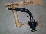 The two red arrows I drew on the last picture (click on the picture to enlarge it) show the clips that hold the pump in it's mount in the tank.This next pic show the wires connected to the old (bad) pump:
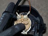 The new pump came with a different type of electrical connector, spade bits with a plastic clip the spade connectors clip in to. The pump is made by Bosch. They supplied everything you need to change the connectors except for the proper crimping tool for the job. I did my best to get them tight, but apparently my best wasn't good enough. I'll get to that in a bit. Here is a pic of the set up on the new pump. I made sure I oriented the wires the way they were on the old pump:
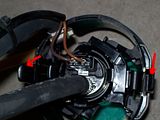 Also, note that I drew red arrows on the previous pic showing the clip locations from the top of the pump.Other than changing the wires, all you have to do is transfer the fuel lines over to the new pump. Installation is just reverse of removal. I would suggest that you replace the rubber gasket to the pump/sending unit. I took a couple of pics to show you how it goes on. I didn't pay attention when I removed the old one, so I had to play with it a bit to get it on right. There is a little indexing mark on the gasket to help you orient it right, I drew green arrows to show when it needs to be to go on correctly.This pic shows the mark:
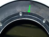 This one shows where it needs to be installed to fit properly (just to the right of the bolt):
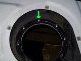 Once you have everything back in and secured, make sure you torque the nuts to 89 inch pounds. I then tried to start the car, but nothing. I tried a couple of more times, but it wouldn't start. I took the pump back out and found that I hadn't done such a good job of crimping the wires, one had come loose when I put it back in the tank. I tried to get the spade connectors out of the little plastic clip without damaging them, but was not successful. I ended up buying some solderless connectors of the same type at Radio Shack and put them on. The plastic clip was no good any longer, but the spade connectors were really tight once I put them on the spades.I put everything back together and tried again, NOTHING. Cranked but no fire. The only other thing that I could think of that could be wrong was that the wires were not hooked up to the right terminals. I took everything back apart, switched the wires, put it back together, and SUCCESS. After being so careful to get the wires in the right position, Bosch swapped the terminal locations. I read through all of the installation material that came with the new pump and there was no mention of any wiring changes at all. At least it works now, and it seems to actually run a bit stronger than before. I think maybe the old pump was weak before it finally gave up.Good Luck if you try this, it isn't really very hard. If things had gone right the first time, the whole job would have taken me about an hour. One other thing, I changed out the fuel filter while I was at it. They recommend doing so in the installation paperwork that comes with the pump.
Hopefully you are reading this to help you figure out how to get those darn gauges, speedometer and tachometer working on your Cavalier. I'm writing a "How To" with pictures to help you out. If you don't know how to get your dash apart, I wrote that up too, just go to the blog post I wrote just before this one.
MAKE SURE YOU READ THIS ALL THE WAY THROUGH BEFORE STARTING THE JOB, JUST SO YOU DON'T GET AHEAD OF YOURSELF.
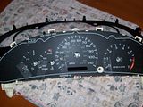
So to this point, you should have your Instrument Cluster in your hot little hands. Here is a picture of what it looks like out of the car, before taking it apart to get to the circuit board.
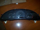 I regret that I forgot to take some pictures of the clips that hold the Cluster together, but once you have yours out of the car, you should be able to figure out how to get it apart. It is pretty obvious.
The main reason the gauges, speedometer and tachometer fail on these cars is due to faulty "Stepper Motors". Long gone is the day of speedometer and tachometer cables and real gauges that took information from sending units. All of that information nowadays is sent by electrical impulses to the Stepper Motor and then displayed on your Cluster.
This is a picture of what the Stepper Motor looks like. The one on the left is the Updated replacement to the one on the right. You can see the GM part number for the new motor... X25.168.
I regret that I forgot to take some pictures of the clips that hold the Cluster together, but once you have yours out of the car, you should be able to figure out how to get it apart. It is pretty obvious.
The main reason the gauges, speedometer and tachometer fail on these cars is due to faulty "Stepper Motors". Long gone is the day of speedometer and tachometer cables and real gauges that took information from sending units. All of that information nowadays is sent by electrical impulses to the Stepper Motor and then displayed on your Cluster.
This is a picture of what the Stepper Motor looks like. The one on the left is the Updated replacement to the one on the right. You can see the GM part number for the new motor... X25.168.
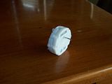
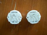 These shots of the Stepper Motors give you a better idea of what they look like.
Front side showing the shaft that the needle attaches to.
These shots of the Stepper Motors give you a better idea of what they look like.
Front side showing the shaft that the needle attaches to.
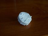
 Rear side showing the two white indexing pins and the four wires you solder to the PCB (printed circuit board).
 Now for the repair steps.
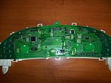
Once you have removed the clear plastic front to the cluster and the back cover that protects the circuit board this is what you will see.
Now for the repair steps.
Once you have removed the clear plastic front to the cluster and the back cover that protects the circuit board this is what you will see.
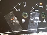
 You can see on the face of the gauges in the previous pictures that I have placed tape near the starting point for the gauges, speedometer and tachometer. This is done to mark the location of the needles prior to pulling them off of the Stepper Motor Shaft. I couldn't find any masking tape, so I used Scotch Tape. Just make sure you can write on the tape. To get the needles to the correct position, you turn them slowly and gently counter clockwise until they stop. That should be the starting or resting point for them. Once you have all the needles to that position, go ahead and mark the needle position on the tape you stuck to the gauge faces.
Here is a close up of my son's cluster so you can see the marks I made. I wish I had taken a photo or two of the cluster prior to removing the needles so you could see how bad they were. The Temperature and Fuel gauge were pointing to the six o'clock position and the Speedometer was registering about 45 mph when the car was parked and not running. The only gauge working was the Tachometer.
You can see on the face of the gauges in the previous pictures that I have placed tape near the starting point for the gauges, speedometer and tachometer. This is done to mark the location of the needles prior to pulling them off of the Stepper Motor Shaft. I couldn't find any masking tape, so I used Scotch Tape. Just make sure you can write on the tape. To get the needles to the correct position, you turn them slowly and gently counter clockwise until they stop. That should be the starting or resting point for them. Once you have all the needles to that position, go ahead and mark the needle position on the tape you stuck to the gauge faces.
Here is a close up of my son's cluster so you can see the marks I made. I wish I had taken a photo or two of the cluster prior to removing the needles so you could see how bad they were. The Temperature and Fuel gauge were pointing to the six o'clock position and the Speedometer was registering about 45 mph when the car was parked and not running. The only gauge working was the Tachometer.
 Once you have the needle positions marked on the tape, it is time to remove the needle from the shaft of each Stepper Motor. The instructions I followed were included with the motors I got on Ebay. Take each needle and turn it slowly counter clockwise until you feel it break loose from the Stepper Motor shaft. Don't worry, it shouldn't break, mine didn't. Once all of the needles are loose, take a Dinner Fork and place it under the base of the needle. Slowly and gently pull up on the needle to get it off of the shaft. It's a bit scary, I know, but it works just as I've written it. Remember which needle came off of which gauge so you put them back on the way they were.
You should be able to pull the cluster face off now. I didn't get a picture of the side of the PCB with the Motors on it. It's not really important since you work off the back side when removing the motors.
The following pictures show you the locations of the Stepper Motors on the business side of the board (soldered joints).
Once you have the needle positions marked on the tape, it is time to remove the needle from the shaft of each Stepper Motor. The instructions I followed were included with the motors I got on Ebay. Take each needle and turn it slowly counter clockwise until you feel it break loose from the Stepper Motor shaft. Don't worry, it shouldn't break, mine didn't. Once all of the needles are loose, take a Dinner Fork and place it under the base of the needle. Slowly and gently pull up on the needle to get it off of the shaft. It's a bit scary, I know, but it works just as I've written it. Remember which needle came off of which gauge so you put them back on the way they were.
You should be able to pull the cluster face off now. I didn't get a picture of the side of the PCB with the Motors on it. It's not really important since you work off the back side when removing the motors.
The following pictures show you the locations of the Stepper Motors on the business side of the board (soldered joints).
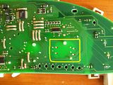 The first picture shows location of the four motors, see the yellow outlines. (If you want to see larger pictures, just click on whatever picture you want to see larger and you will see the larger size.) If you look closely, you can see the outlines of the motors through the PCB.
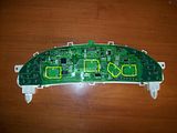
The second picture is just a close up of one of the motors on the board. You can see the outline of the motor more clearly in this picture. You can also see the two indexing pins that locate the motor properly on the PCB. I put a little red dot next to the soldering points on the PCB for the motor. These are the spots you will need to work on. It is quite easy to locate these spots for each of the four motors if you have the PCB in front of you.
Now all you have to do is remove the motors and solder in the new ones. I know, it sounds like a tough job, but it really isn't. I have a very basic knowledge of soldering and it only took me about 20 minutes to do the job.
What you have to have to complete the job is a soldering iron and some way to de-solder the joints. I bought a De-soldering Iron at Radio Shack for $11. It is extremely easy to use and makes the job a snap. I would guess it took me less than five minutes to remove all of the motors from the PCB using the De-soldering Iron.
The first picture shows location of the four motors, see the yellow outlines. (If you want to see larger pictures, just click on whatever picture you want to see larger and you will see the larger size.) If you look closely, you can see the outlines of the motors through the PCB.
The second picture is just a close up of one of the motors on the board. You can see the outline of the motor more clearly in this picture. You can also see the two indexing pins that locate the motor properly on the PCB. I put a little red dot next to the soldering points on the PCB for the motor. These are the spots you will need to work on. It is quite easy to locate these spots for each of the four motors if you have the PCB in front of you.
Now all you have to do is remove the motors and solder in the new ones. I know, it sounds like a tough job, but it really isn't. I have a very basic knowledge of soldering and it only took me about 20 minutes to do the job.
What you have to have to complete the job is a soldering iron and some way to de-solder the joints. I bought a De-soldering Iron at Radio Shack for $11. It is extremely easy to use and makes the job a snap. I would guess it took me less than five minutes to remove all of the motors from the PCB using the De-soldering Iron.
Here is a picture of the De-soldering Iron.
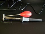
As you can see, it is nothing more than a soldering iron with a suction bulb attached. You squeeze the bulb, put the tip on the joint, let it heat for about 3-4 seconds and let the bulb go and remove the tip. Very simple. Just follow the instructions with the Iron. Also, there are several very good de-soldering videos on youtube you can watch, I found several, so go there and look if you want more information.
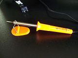
Once you have all the motors removed, you need to get the new motors in place for soldering. Make sure the wire pins go into their respective holes without folding under. They need to be sticking out through the holes to solder them in place. Just take your time, it isn't hard. Once the new motors are back in place, solder them all up. Again, youtube has several good soldering videos to help you out. I bought a nice little 30w Iron at Harbor Freight for $4 and it worked perfectly.
Here is a picture of the one I bought.
Make sure you have a pencil type tip, it makes it easier to get around those small joints. Here is a close up of the pencil tip:
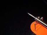
When soldering on a PCB, use 60/40 ROSIN core solder. Do NOT use acid core solder unless you want to ruin your circuit board. I bought some .032" solder. The smaller diameter makes it melt quicker, not as much mass to heat up.
This is the solder I used:
 The soldering probably took me about 10 minutes or so to complete.
Once the soldering is done, you can put the Cluster back together. Just reverse the steps you did to take it apart. When you are ready to put the gauge needles back on, here is how you do it.
Put the needle on the shaft at the 12 o'clock position and push it on. Once they are all installed, turn the needle counter clockwise until you line up the needle with the mark you made on the tape. When you get to the mark, stop. That should be where each needle is at rest. You can put the rest of the cluster back together and get ready to put it back into the car.
As I stated in my previous blog entry on removal of the Dash on the Cavalier. I removed the fuses for the Instrument Cluster and the Air Bags. If you didn't follow my instructions regarding the Dash, I would suggest you remove those two fuses just to be safe.
Now, go out to the car and put the Cluster back where it is supposed to be and hook up the plug to the back. Now, put the Instrument Cluster fuse back in and you should see your needles set themselves to their resting points. If everything looks good, go ahead and put everything back together. When we did this on my son's car, the Speedometer was reading about 1 mph. We pulled the fuse, removed the cluster and opened it up. Moved the needle a little bit more counter clockwise and then put it back together. This time it was in the right spot.
We finished up by putting the dash back together and then starting the car. Everything seemed to be working correctly. Here is a picture of the Cluster while we were driving around checking it out.
The soldering probably took me about 10 minutes or so to complete.
Once the soldering is done, you can put the Cluster back together. Just reverse the steps you did to take it apart. When you are ready to put the gauge needles back on, here is how you do it.
Put the needle on the shaft at the 12 o'clock position and push it on. Once they are all installed, turn the needle counter clockwise until you line up the needle with the mark you made on the tape. When you get to the mark, stop. That should be where each needle is at rest. You can put the rest of the cluster back together and get ready to put it back into the car.
As I stated in my previous blog entry on removal of the Dash on the Cavalier. I removed the fuses for the Instrument Cluster and the Air Bags. If you didn't follow my instructions regarding the Dash, I would suggest you remove those two fuses just to be safe.
Now, go out to the car and put the Cluster back where it is supposed to be and hook up the plug to the back. Now, put the Instrument Cluster fuse back in and you should see your needles set themselves to their resting points. If everything looks good, go ahead and put everything back together. When we did this on my son's car, the Speedometer was reading about 1 mph. We pulled the fuse, removed the cluster and opened it up. Moved the needle a little bit more counter clockwise and then put it back together. This time it was in the right spot.
We finished up by putting the dash back together and then starting the car. Everything seemed to be working correctly. Here is a picture of the Cluster while we were driving around checking it out.
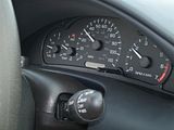 As you can see, everything seemed to be working properly. We used a GPS to make sure the Speedometer was working right and it was right on.
This little repair could cost you upwards of $500 if you have someone repair it for you. Even with buying the Soldering Iron, De-Soldering Iron, Solder and Motors, we had just under $60 into the repair.
Good Luck if you try this out.
As you can see, everything seemed to be working properly. We used a GPS to make sure the Speedometer was working right and it was right on.
This little repair could cost you upwards of $500 if you have someone repair it for you. Even with buying the Soldering Iron, De-Soldering Iron, Solder and Motors, we had just under $60 into the repair.
Good Luck if you try this out.
An FYI... This is part one of a two part blog entry. The second part will cover how I repaired the Instrument Cluster on the 05 Cavalier.I really enjoy using the Internet. You can find all sorts of information about all kinds of things. I spent several hours surfing and searching for information on how to remove the dashboard on a 2005 Chevy Cavalier, but couldn't find a good step by step instruction on how to do it. Hence this blog entry.
The reason I wanted to know how to do it was so I could remove the Instrument Cluster to repair the Speedometer, Fuel and Temperature gauges on the car.The car belongs to my son. We were talking one day and he said that his Speedometer had stopped working, along with the Fuel and Temp gauges. One thing lead to another and I was on the Internet looking for fixes. I first came across some guys who talked about the "Stepper Motors" being bad. Apparently, GM used a very bad batch of these "Stepper Motors" in a whole bunch of cars, not just the Cavalier. I located some Speedometer Repair services on Ebay that offered their services for $90 and up. The $90 service was just to repair one Stepper Motor, if you wanted more done, it was at least $10 per motor more. I kept on looking and found some decent "How to" sites that gave a bit of information on how to do the repair for yourself. I'm all into that (just read through more of my blog posts about my other adventures with my BMW's). So I decided to try and do this myself. I found a seller on Ebay that was selling the upgraded GM "Stepper Motors" for a decent price. I needed four to do the job... replacing the bad Speedometer, Fuel and Temp gauge and just so I wouldn't have to do it again, I would replace the Tachometer motor also, even though it was still working.Once the Motors arrived, I had everything I needed, except for good instructions on how to get the Instrument Cluster out of the car. Now, there will be these instructions for you to use if you need to take yours apart.The first thing you need to do is locate all of the screws that hold the top of the dash in place. Below are some pictures I took of their locations. Just follow the comments I put at the top of each picture.I started by removing the end trim pieces of the dash.This is the drivers side end. In the picture you can see the two yellow arrows, these are the trim pieces that just pry off. There is a screw in the green circle that has to be removed. The three red circles show the mounting points for the large trim piece. The small trim piece is actually the door to the fuse box.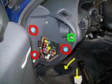 This next picture is the end on the passenger side of the car. The screw in the green circle needs to come off. The mounting spots for the trim on this side are those blue receptacles. The trim just pulls off.
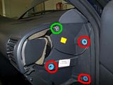 The next screws I removed came from the glove box area. Open the glove box and you will see two screws near the upper edge of the box, circled in green in the picture. You need to remove these.
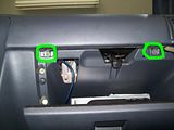 It's hard to get a full shot of the plastic bezel that you are removing to get to the cluster when it's still in the car. Here is a shot of it removed, so you can see what has to come out.
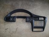 Just so you know, in the bezel picture, there are two plugs you have to disconnect to completely get it out of the car. If you look at near the center of the bezel you will see a small round hole, that is where the Cigarette lighter fits. There is a plug to it. There is a plug to the light dimmer switch also that has to be removed. Both plugs have little retaining clips you have to manipulate to unplug them.There are still two more screws that you will need to remove before the bezel can come out. These two screws are located on either side of the Instrument Cluster on the top. In the pictures you can see their locations. The one on the right side is a bit of a bear to get out.This is the left side of the bezel. The screw is located inside where I drew the red circle (the other circles will be explained later). This screw installs from the top, so you have to make sure that the other screws and clips are loose so you can get to this one.
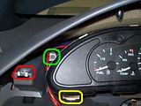 This is the right side of the bezel. The screw is located where I drew the red circle (same thing about the other circles). This screw also installs from the top. I would suggest that this be the last screw you remove, since it's the hardest to get to.
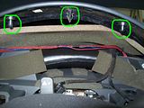
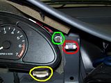 All of these screws use a 7mm socket. The rest of the bezel is just pried off. I used two different sized putty knives to do the prying. You have to pry up around the cluster to get to the last two screws. These two pics show the clips (same clips, just different camera angles) that need to come out to get to the screws (green circles).
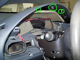
 By getting these clips released and up, it makes it much easier to get to the screws. Just make sure to remove the other screws first.These pictures give you an idea of where the clips are located along the whole bezel.This picture shows the area around the radio and climate control unit. The red arrow is a clip that was a bit difficult to see even with everything else loose. I put a screwdriver in behind the bezel at that point and pried outward and it finally released. The two green arrows are clips that released fairly easy. The yellow arrow points to the location of the last screw on the right side of the Cluster.
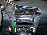 This picture shows all of the various clips, mounting points and screw positions on top of the bezel from the top. All of the circled parts are involved in securing it to the dash.
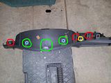 Once all of the clips and screw are out or released, you only have one more thing to do to get the bezel out. You need to remove the top plastic cover to the steering wheel. If you look between your steering wheel and the bezel, there is a plastic cover where the "Emergency Flasher" button sticks out. This is a two piece cover that is split down the side so it can be removed if necessary. Find the joint where it connects and use one of your putty knives to open it, sort of like a clam. It popped right open with very little pressure on my son's car. Pull the top off and you should then be able to get the bezel out. You have to sort of finesse it out, but it does come out. Make sure you remove the two plugs for the Cig Lighter and Dimmer switch.That takes care of removing the bezel. This next part is a bit easier and only takes a few minutes.There are two screws that hold the Cluster in place. Here are those two pictures from before that I said I would explain about the other circles. The green circles show the location of the screws that need to be removed to get the Cluster out. The yellow circles show the mounting points on the bottom of the cluster. If you look closely, you can see two white pieces that are nipples on the Cluster that locate the Cluster in the opening of the bezel. The nipples fit in holes in the dash.Prior to removing the Cluster I removed the fuses for the Instrument Cluster and the Air Bags, just to make sure I didn't short something out. Make sure you put them back it once you have everything put back together.Once the screws are removed, you can tilt the top of the Cluster towards you and it will start to come out. Manipulate it a bit and you can get the nipples out of the holes. Once it's clear, you just have to unclip the plug to the Cluster that is located at the center/top of the Cluster.That does it for this part. I will blog another post soon about the actual repair of the cluster.


