Sunday, March 21, 2010

Repairing the Instrument Cluster on a 2005 Chevy Cavalier

Hopefully you are reading this to help you figure out how to get those darn gauges, speedometer and tachometer working on your Cavalier. I'm writing a "How To" with pictures to help you out. If you don't know how to get your dash apart, I wrote that up too, just go to the blog post I wrote just before this one.

MAKE SURE YOU READ THIS ALL THE WAY THROUGH BEFORE STARTING THE JOB, JUST SO YOU DON'T GET AHEAD OF YOURSELF.

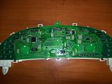
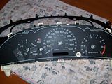
So to this point, you should have your Instrument Cluster in your hot little hands. Here is a picture of what it looks like out of the car, before taking it apart to get to the circuit board.
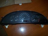
Photobucket

I regret that I forgot to take some pictures of the clips that hold the Cluster together, but once you have yours out of the car, you should be able to figure out how to get it apart. It is pretty obvious.

The main reason the gauges, speedometer and tachometer fail on these cars is due to faulty "Stepper Motors". Long gone is the day of speedometer and tachometer cables and real gauges that took information from sending units. All of that information nowadays is sent by electrical impulses to the Stepper Motor and then displayed on your Cluster.

This is a picture of what the Stepper Motor looks like. The one on the left is the Updated replacement to the one on the right. You can see the GM part number for the new motor... X25.168.
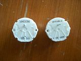
Photobucket

These shots of the Stepper Motors give you a better idea of what they look like.
Front side showing the shaft that the needle attaches to.
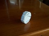
Photobucket

Rear side showing the two white indexing pins and the four wires you solder to the PCB (printed circuit board).
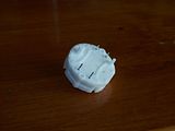
Photobucket

Now for the repair steps.

Once you have removed the clear plastic front to the cluster and the back cover that protects the circuit board this is what you will see.
Photobucket

Photobucket

You can see on the face of the gauges in the previous pictures that I have placed tape near the starting point for the gauges, speedometer and tachometer. This is done to mark the location of the needles prior to pulling them off of the Stepper Motor Shaft. I couldn't find any masking tape, so I used Scotch Tape. Just make sure you can write on the tape. To get the needles to the correct position, you turn them slowly and gently counter clockwise until they stop. That should be the starting or resting point for them. Once you have all the needles to that position, go ahead and mark the needle position on the tape you stuck to the gauge faces.

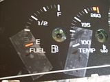
Here is a close up of my son's cluster so you can see the marks I made. I wish I had taken a photo or two of the cluster prior to removing the needles so you could see how bad they were. The Temperature and Fuel gauge were pointing to the six o'clock position and the Speedometer was registering about 45 mph when the car was parked and not running. The only gauge working was the Tachometer.
Photobucket

Once you have the needle positions marked on the tape, it is time to remove the needle from the shaft of each Stepper Motor. The instructions I followed were included with the motors I got on Ebay. Take each needle and turn it slowly counter clockwise until you feel it break loose from the Stepper Motor shaft. Don't worry, it shouldn't break, mine didn't. Once all of the needles are loose, take a Dinner Fork and place it under the base of the needle. Slowly and gently pull up on the needle to get it off of the shaft. It's a bit scary, I know, but it works just as I've written it. Remember which needle came off of which gauge so you put them back on the way they were.

You should be able to pull the cluster face off now. I didn't get a picture of the side of the PCB with the Motors on it. It's not really important since you work off the back side when removing the motors.

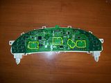
The following pictures show you the locations of the Stepper Motors on the business side of the board (soldered joints).
Photobucket

Photobucket

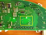
The first picture shows location of the four motors, see the yellow outlines. (If you want to see larger pictures, just click on whatever picture you want to see larger and you will see the larger size.) If you look closely, you can see the outlines of the motors through the PCB.

The second picture is just a close up of one of the motors on the board. You can see the outline of the motor more clearly in this picture. You can also see the two indexing pins that locate the motor properly on the PCB. I put a little red dot next to the soldering points on the PCB for the motor. These are the spots you will need to work on. It is quite easy to locate these spots for each of the four motors if you have the PCB in front of you.

Now all you have to do is remove the motors and solder in the new ones. I know, it sounds like a tough job, but it really isn't. I have a very basic knowledge of soldering and it only took me about 20 minutes to do the job.

What you have to have to complete the job is a soldering iron and some way to de-solder the joints. I bought a De-soldering Iron at Radio Shack for $11. It is extremely easy to use and makes the job a snap. I would guess it took me less than five minutes to remove all of the motors from the PCB using the De-soldering Iron.

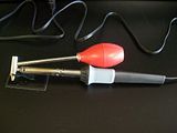
Here is a picture of the De-soldering Iron.
Photobucket

As you can see, it is nothing more than a soldering iron with a suction bulb attached. You squeeze the bulb, put the tip on the joint, let it heat for about 3-4 seconds and let the bulb go and remove the tip. Very simple. Just follow the instructions with the Iron. Also, there are several very good de-soldering videos on youtube you can watch, I found several, so go there and look if you want more information.


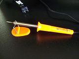
Once you have all the motors removed, you need to get the new motors in place for soldering. Make sure the wire pins go into their respective holes without folding under. They need to be sticking out through the holes to solder them in place. Just take your time, it isn't hard. Once the new motors are back in place, solder them all up. Again, youtube has several good soldering videos to help you out. I bought a nice little 30w Iron at Harbor Freight for $4 and it worked perfectly.

Here is a picture of the one I bought.
Photobucket

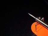
Make sure you have a pencil type tip, it makes it easier to get around those small joints. Here is a close up of the pencil tip:
Photobucket

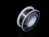
When soldering on a PCB, use 60/40 ROSIN core solder. Do NOT use acid core solder unless you want to ruin your circuit board. I bought some .032" solder. The smaller diameter makes it melt quicker, not as much mass to heat up.


This is the solder I used:
Photobucket

The soldering probably took me about 10 minutes or so to complete.

Once the soldering is done, you can put the Cluster back together. Just reverse the steps you did to take it apart. When you are ready to put the gauge needles back on, here is how you do it.

Put the needle on the shaft at the 12 o'clock position and push it on. Once they are all installed, turn the needle counter clockwise until you line up the needle with the mark you made on the tape. When you get to the mark, stop. That should be where each needle is at rest. You can put the rest of the cluster back together and get ready to put it back into the car.

As I stated in my previous blog entry on removal of the Dash on the Cavalier. I removed the fuses for the Instrument Cluster and the Air Bags. If you didn't follow my instructions regarding the Dash, I would suggest you remove those two fuses just to be safe.

Now, go out to the car and put the Cluster back where it is supposed to be and hook up the plug to the back. Now, put the Instrument Cluster fuse back in and you should see your needles set themselves to their resting points. If everything looks good, go ahead and put everything back together. When we did this on my son's car, the Speedometer was reading about 1 mph. We pulled the fuse, removed the cluster and opened it up. Moved the needle a little bit more counter clockwise and then put it back together. This time it was in the right spot.

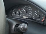
We finished up by putting the dash back together and then starting the car. Everything seemed to be working correctly. Here is a picture of the Cluster while we were driving around checking it out.
Photobucket

As you can see, everything seemed to be working properly. We used a GPS to make sure the Speedometer was working right and it was right on.

This little repair could cost you upwards of $500 if you have someone repair it for you. Even with buying the Soldering Iron, De-Soldering Iron, Solder and Motors, we had just under $60 into the repair.

Good Luck if you try this out.
Saturday, March 20, 2010

Dashboard and Instrument Cluster Removal on a 2005 Chevy Cavalier

An FYI... This is part one of a two part blog entry. The second part will cover how I repaired the Instrument Cluster on the 05 Cavalier.

I really enjoy using the Internet. You can find all sorts of information about all kinds of things. I spent several hours surfing and searching for information on how to remove the dashboard on a 2005 Chevy Cavalier, but couldn't find a good step by step instruction on how to do it. Hence this blog entry.

The reason I wanted to know how to do it was so I could remove the Instrument Cluster to repair the Speedometer, Fuel and Temperature gauges on the car.


The car belongs to my son. We were talking one day and he said that his Speedometer had stopped working, along with the Fuel and Temp gauges.

One thing lead to another and I was on the Internet looking for fixes. I first came across some guys who talked about the "Stepper Motors" being bad. Apparently, GM used a very bad batch of these "Stepper Motors" in a whole bunch of cars, not just the Cavalier. I located some Speedometer Repair services on Ebay that offered their services for $90 and up. The $90 service was just to repair one Stepper Motor, if you wanted more done, it was at least $10 per motor more.

I kept on looking and found some decent "How to" sites that gave a bit of information on how to do the repair for yourself. I'm all into that (just read through more of my blog posts about my other adventures with my BMW's). So I decided to try and do this myself. I found a seller on Ebay that was selling the upgraded GM "Stepper Motors" for a decent price. I needed four to do the job... replacing the bad Speedometer, Fuel and Temp gauge and just so I wouldn't have to do it again, I would replace the Tachometer motor also, even though it was still working.

Once the Motors arrived, I had everything I needed, except for good instructions on how to get the Instrument Cluster out of the car. Now, there will be these instructions for you to use if you need to take yours apart.

The first thing you need to do is locate all of the screws that hold the top of the dash in place. Below are some pictures I took of their locations. Just follow the comments I put at the top of each picture.

I started by removing the end trim pieces of the dash.

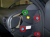
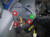
This is the drivers side end. In the picture you can see the two yellow arrows, these are the trim pieces that just pry off. There is a screw in the green circle that has to be removed. The three red circles show the mounting points for the large trim piece. The small trim piece is actually the door to the fuse box.
Photobucket

This next picture is the end on the passenger side of the car. The screw in the green circle needs to come off. The mounting spots for the trim on this side are those blue receptacles. The trim just pulls off.
Photobucket

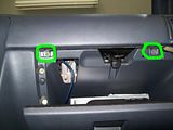
The next screws I removed came from the glove box area. Open the glove box and you will see two screws near the upper edge of the box, circled in green in the picture. You need to remove these.
Photobucket

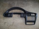
It's hard to get a full shot of the plastic bezel that you are removing to get to the cluster when it's still in the car. Here is a shot of it removed, so you can see what has to come out.
Photobucket

Just so you know, in the bezel picture, there are two plugs you have to disconnect to completely get it out of the car. If you look at near the center of the bezel you will see a small round hole, that is where the Cigarette lighter fits. There is a plug to it. There is a plug to the light dimmer switch also that has to be removed. Both plugs have little retaining clips you have to manipulate to unplug them.

There are still two more screws that you will need to remove before the bezel can come out. These two screws are located on either side of the Instrument Cluster on the top. In the pictures you can see their locations. The one on the right side is a bit of a bear to get out.

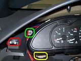
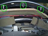
This is the left side of the bezel. The screw is located inside where I drew the red circle (the other circles will be explained later). This screw installs from the top, so you have to make sure that the other screws and clips are loose so you can get to this one.
Photobucket

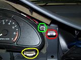
This is the right side of the bezel. The screw is located where I drew the red circle (same thing about the other circles). This screw also installs from the top. I would suggest that this be the last screw you remove, since it's the hardest to get to.
Photobucket

All of these screws use a 7mm socket. The rest of the bezel is just pried off. I used two different sized putty knives to do the prying. You have to pry up around the cluster to get to the last two screws. These two pics show the clips (same clips, just different camera angles) that need to come out to get to the screws (green circles).
Photobucket

Photobucket

By getting these clips released and up, it makes it much easier to get to the screws. Just make sure to remove the other screws first.

These pictures give you an idea of where the clips are located along the whole bezel.

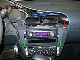
This picture shows the area around the radio and climate control unit. The red arrow is a clip that was a bit difficult to see even with everything else loose. I put a screwdriver in behind the bezel at that point and pried outward and it finally released. The two green arrows are clips that released fairly easy. The yellow arrow points to the location of the last screw on the right side of the Cluster.
Photobucket

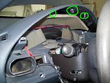
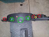
This picture shows all of the various clips, mounting points and screw positions on top of the bezel from the top. All of the circled parts are involved in securing it to the dash.
Photobucket

Once all of the clips and screw are out or released, you only have one more thing to do to get the bezel out. You need to remove the top plastic cover to the steering wheel. If you look between your steering wheel and the bezel, there is a plastic cover where the "Emergency Flasher" button sticks out. This is a two piece cover that is split down the side so it can be removed if necessary. Find the joint where it connects and use one of your putty knives to open it, sort of like a clam. It popped right open with very little pressure on my son's car. Pull the top off and you should then be able to get the bezel out. You have to sort of finesse it out, but it does come out. Make sure you remove the two plugs for the Cig Lighter and Dimmer switch.

That takes care of removing the bezel. This next part is a bit easier and only takes a few minutes.

There are two screws that hold the Cluster in place. Here are those two pictures from before that I said I would explain about the other circles. The green circles show the location of the screws that need to be removed to get the Cluster out. The yellow circles show the mounting points on the bottom of the cluster. If you look closely, you can see two white pieces that are nipples on the Cluster that locate the Cluster in the opening of the bezel. The nipples fit in holes in the dash.
Photobucket

Photobucket

Prior to removing the Cluster I removed the fuses for the Instrument Cluster and the Air Bags, just to make sure I didn't short something out. Make sure you put them back it once you have everything put back together.

Once the screws are removed, you can tilt the top of the Cluster towards you and it will start to come out. Manipulate it a bit and you can get the nipples out of the holes. Once it's clear, you just have to unclip the plug to the Cluster that is located at the center/top of the Cluster.

That does it for this part. I will blog another post soon about the actual repair of the cluster.